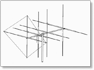

The Lower-outer was to be added after the assembly was in place. The Full-length and the Inner mast were assembled with stainless steel screws. The Lower Outer (EMT) was positioned to reinforce the lower part of the mast, up to ~ 4 feet above the tower top. Also, the Inner pipe did not extend all the way to the mast bottom, but there was pipe overlap inside the tower. In other words, the top 4.5 feet consisted of only the SS-20 pipe. The Inner was positioned inside the Full-length Outer, such that it did not reach the top ~ 4.5 feet. Top portion consisted of one pipe (SS-20).


At that time, the existing mast was 10.5 feet of SS-20 (heavy duty), 1 & 3/8 inch outer diameter top fence rail. For maximum stacking gain, individual antennas with higher gain require increased stack spacing. If higher gain antennas were to occupy the top position on the tower, then a taller mast may be required. Over the next few weeks, other VHF antenna configurations were mounted on the test mast and reception observed. So dB values were commonly provided in dB, as actually measured, with respect to a dipole (dBd).Ī pair of VIP-306’s was purchased for evaluation and potentially for stacking.īelow, is an image of a single VIP-306 installed at the test location, aimed towards the main tower.
Wilson shooting star antenna series#
In the late 1960's when the VIP series were designed, computer simulation (dBi) was virtually non-existant. The VIP-307 version had a bit more gain but was no longer available. This required amount of increased gain (7 dB) essentially ruled out a quad stack of YA-1713’s.Ī quad stack of YA-1713s (2 horizontal, vertically stacked above 2 horizontal, or even a diamond stacked quad) would at best provide ~3dB gain above a dual stack.Īt the time, the highest gain for commercially available VHF antenna was Jerrold/Wade VIP-306 (specified gain of 12 dB on Channel 11). For several weeks, reception of these two stations was checked daily.Īn additional two YA-1713’s were purchased for possibility of a installing a quad stacked arrangement of YA-1713’s.Īn additional gain of 7 dB, above that provided by the stacked YA-1713’s, may be required for reliable reception of WHAS-11. This calibration of CM-7000 was used to help evaluate the two stations’ signals, hoping to make antenna changes for potentially better reception. The signal goodness indication on a CM-7000 DTV converter was calibrated using a Signal Level Meter (~1.5 dB per each 10% indication for channel 11). WBNA (ION) Channel 8, 24.5 kW, at ~80 miles, TVfool Noise Margin -7.0 dBĪnd also interesting, for short periods of times, Louisville’s WHAS channel 11 (16.4 kW, at 101 miles) could be received, but was not actually watchable. Then, it was realized that for part of the time, a Louisville KY VHF station could be received and was occasionally watchable. Previously mentioned was that the stacked YA-1713’s on the main tower were not much use after WKYT moved from Channel 13 to Channel 36. This particular 8-bay antenna as an old Channel Master antenna.

One 8-bay was copy of a 4228 made at a regional factory, and
Wilson shooting star antenna tv#
Without providing any information, I asked the experienced TV antenna man to identify the antennas. Inside on one wall, were six 8-bays hanging side-by-side. Last year, a long-time retired TV antenna installer was at my shop (garage in the earlier photo). And, I thought it was a Channel Master antenna. That business only handled Channel Master TV antennas. When the antenna was purchased, I was working as a technician at a regional TV repair & Motorola 2-Way radio service center. So, guess the design change occurred before 1973. Since your comment, I looked at a 1973 Channel Master catalog, it shows the 4228 as is commonly known. It appears that the "original" CM-4228 is a design evolution of this model?.


 0 kommentar(er)
